Describe the Connection Setup for Vapor Recovery
Vapor Recovery Towers serve as the last designated pressure vessel to collect vapors from produced liquids to later be recovered and discharged into a sales line by a vapor recovery unit. The gauges are connected as they normally are with the high side manifold hose connected to the liquid line service valve and the low side manifold hose connected to the suction service valve.
2
0 psig for very high pressure refrigerants.

. API publications may be used by anyone desiring to do so. Set the recovery machine to recover. Connect Casing to Vapor Recovery Unit.
VRUs are finding wider application at production sites with multiple oil or condensate storage tanks that have significant vapor emissions. List methods of speeding up refrigerant recovery. Dual rotary screws compressor packages are set in tandem to move 15 MMSCFD of 2500-2600 BTUcu ft.
Quantify the volume of vapor emissions 3. For increased flash gas production utilize OTAs VRT Max. Fluorescent dye added to a refrigeration system shows up to indicate the location of a leak when exposed to ultraviolet light.
The discharge or outlet of the recovery machine is connected to the discharge service valve on the compressor. PURGE THE HOSES OF AIR this is done a little bit differently than in direct recovery a. 28-16 Describe the connection setup for vapor recovery.
Identify possible locations for VRU installation 2. The vapor valve on the recovery cylinder is connected to the suction side or inlet of the recovery machine. This PRO fact sheet discusses Connecting Casing to Vapor Recovery Unit.
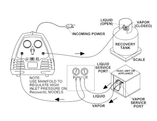
When the unit is started vapor is drawn out of the recovery tank from the vapor port of the tank and condensed in the recovery unit. VRU systems can be employed in a wide range of chemical industries with several variants available. The gauges are connected as they normally are with the high side manifold hose connected to the liquid line service valve and the low side manifold hose connected to the suction service valve.
List the recovery levels for Type II systems using a recovery system manufactured on or after November 15 1993. Vapor recovery is the process of collecting the vapors of gasoline and other fuels so that they do not escape into the atmosphere. The vapor valve on the recovery cylinder is connected to the suction side or inlet of the recovery machine.
The center manifold hose connects to the inlet of the recovery unit and the outlet of the recovery unit connects to the vapor port on the recovery cylinder. 0 psig for systems with less than 200 pounds of a high pressure refrigerant. Condensate recovery more than doubled PDVSa estimates.
This is often done at filling stations to reduce noxious and potentially explosive fumes and pollution. This practice takes advantage of the similarities in gas pressure composition and rates between tank emissions and. Vapor 4 to 6 Inches Vapor Hose Fuel Hose Coaxial Delivery Elbow Coaxial Fill Pipe Adapter Tank Coaxial Stage I vapor recovery uses a drop tube with a narrow top section to create a vapor pathway between the drop tube and the fill pipe.
For example a vapor recovery system for storage tanks can be. Vapor Recovery from Truck Loading. This document is one of the Partner Reported Opportunities PRO for Reducing Methane Emissions fact sheets developed by the Natural Gas STAR Program to promote the use of technologies and best practices that reduce methane emissions.
VRTs insulate the VRU from vapor pressure surges and is more tolerant to higher and lower pressures. Normally you have an internal pipe in each compartment open in the tanker vapor space and continued outside of the compartment s to. The liquid line service valve or king valve is connected to the liquid valve on the recovery cylinder.
Determine the cost of VRU project 5. The gauges are connected as they normally are with the high side manifold hose connected to the liquid line service valve and the low side manifold hose connected to the suction service valve. The total installation requires a capital in-vestment of approximately 800000.
In your case the vapor return line is connected to the bottom of the road tanker but can be in the top or piped externally to an accessible point. What are we trying to recover How do we recover it compression Five Steps for Assessing VRU Central Facility 1. Describe the connection setup for push-pull liquid recovery.
Describe the connection setup for push-pull liquid recovery. A special coaxial delivery elbow must be used to complete the fuel and vapor pathways to the fuel-delivery truck. I vapor recovery the vapor recovery and product adaptors and the method of connection with the deliveiy elbow shall be designed so as to prevent the over-tightening or loosening of fittings during.
Of bottom-loading and vapor-recovery systems of MC-306 DOT-406 tank motor vehicles. 10 hg vacuum for systems with 200 pounds or more of a high pressure refrigerant. LeakFinder Fluorescent Leak Detection Dyes are the perfect solution for anyone working on a vehicles total system.
To prevent all vapor losses requires the addition of 1800000 ft3 of vapor storage composed of twelve 150000-ft3 vapor tanks. 90 28-15 Describe the connection setup for push-pull liquid recovery. The discharge or outlet of the recovery machine is connected to the discharge service valve.
The negative pressure created in the storage tank by fuel being drawn combined with the pressure in the cars fuel tank caused by the inflow is. The liquid line service valve or king valve is connected to the liquid valve on the recovery cylinder. The suction line of the recovery unit is connected to the vapor fitting on the recovery tank and a connection is then made from the discharge outlet of the recovery unit back to the system.
Setup hoses as shown in the diagram. Every effort has been made by the Institute to assure the accuracy and reliability of the data contained in them. Describe the connection setup for vapor recovery.
Start with all valves closed recovery cylinder recovery machine manifold hoses 2. Gr2vessels Mechanical 20 Sep 13 0208. ZEROTARE the refrigerant scale.
What is the maximum safe pressure to impose on any lowpressure system. Methane emissions is to connect the casinghead vent to an existing vapor recovery unit VRU. Vapor valve connects to suction side liquid line to liquid valve Describe the connection setup for vapor recovery.
The center manifold hose connects to the inlet of the recovery unit and the outlet of the recovery unit connects to the vapor port on the recovery cylinder. Describe the connection setup for vapor recovery. Determine the value of the recovered emissions 4.
V If a gauge well separate from the fill tube is used it shall. Connecting vapor-line system would recover half of the filling losses or approximately 42 of the total losses. A Vapor Recovery Unit VRU is a set-up designed to remove unwanted vapors present in crude oil or distillate tanks allowing operators to comply with prevailing emission regulations.
Service Clinic Effective Refrigerant Recovery Techniques Contracting Business
Vapour Recovery System An Overview Sciencedirect Topics

Vapor Recovery Wikipedia
No comments for "Describe the Connection Setup for Vapor Recovery"
Post a Comment